

Solar street light wiring diagram
First, the working principle of the street light control system: the photovoltaic battery charges the battery during the day, and the battery provides electricity for the street light at night. So the battery will constitute a charge and discharge cycle. The solar street light lighting control circuit includes photovoltaic battery, battery, street light and controller.
1. The design uses the AT89S52 single-chip microcomputer as the intelligent core module. The peripheral circuit mainly includes a solar cell voltage sampling module, a battery voltage sampling module, a keyboard circuit module, an LED display module, and a charge and discharge control module.
2. Figure 1 is a structural design diagram of a solar street light controller.
Turn left | turn right

3. The solar street light controller selects ATMEL's 8-bit microcontroller AT89S52 as the core intelligent control module, which has the characteristics of low power consumption and high performance as a whole.
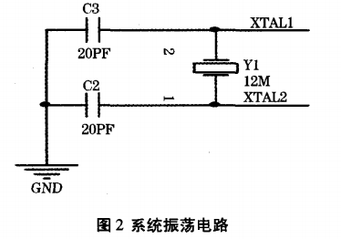
Second, the microcontroller oscillation circuit
1. The single-chip oscillator circuit is shown in Figure 2.
Turn left | turn right
2. Summary of design schemes of solar street light control circuits
Third, the reset circuit
1. The reset circuit is shown in Figure 3. The circuit structure is simple, stable and reliable.
Turn left | turn right

2. The normal operating voltage of the system is 5V. The system uses 12V / 24V lead-acid batteries for power supply. The battery voltage is unstable, so the power supply needs to be regulated. This system uses a LM7805 three-terminal regulator, and its input voltage can guarantee a stable + 5V when the input voltage is 5 ~ 24V. LM7805 requires only a few external components to form a regulated power supply, which is very convenient to use and stable and reliable. The system power circuit is shown in Figure 4.
Turn left | turn right

3. Solar cell sampling and battery sampling play a very important role in the normal operation of the system.
3.1. The solar street light controller should reasonably control the battery charge and discharge, that is, the battery and solar panel voltages need to be sampled. To this end, the AT89S52 single chip microcomputer must be connected to an A / D conversion module to convert the voltage into a digital signal. The system selects a v / F conversion chip LM331 to form a digital-to-analog conversion circuit J.
3.2 In the system sampling design, in order to prevent the AT89S52 program from flying or crashing due to external factors and improving system stability, a single-channel high-speed optoelectronic isolator 6n137J needs to be added between the LM331 and the microcontroller. FIG. 5 is a sampling circuit diagram of a solar panel. The system battery sampling and solar panel sampling circuits are the same.
Turn left | turn right

4. The block diagram of the lighting system is shown in Figure 1.
Turn left | turn right

5, Figure 1 LED solar energy-saving lamp lighting system block diagram
5.1. The single-chip computer detects the voltage sent by the solar power generation board through the detection circuit, and judges whether it is dark from the conversion value of a group of A / DCl.
5.2 When the light is sufficient, the electricity from the solar power generation board will be sent to the constant voltage circuit. At this time, the single-chip microcomputer will also monitor the charge of the rechargeable battery by its A / DC1 conversion value. To indicate the charge of the rechargeable battery. The single chip microcomputer charges the rechargeable battery in a constant voltage manner. As long as the output voltage value of the constant voltage circuit is set according to the specifications of the rechargeable battery, the situation of overcharging and damage of the battery will not occur.
5.3. When the light is insufficient (dark), the single chip microcomputer detects that the voltage issued by the solar power generation panel is close to zero through the converted value of A / DC1. At this time, the single chip microcomputer will judge whether it is lit according to the converted value of A / DC1 LED lights, when the value converted by this A / DC1 is lower than a certain threshold value, the smaller the value, the microcontroller will output a PWM signal with a wider pulse width, so that the brightness of the LED lights is brighter.
5.4. If the rechargeable battery is only charged by the solar battery, its charge may not be enough to provide the LED light to light up all night. Therefore, we expect that the solar light will only light up for about 6 hours after nightfall, and about 12 o'clock in the evening has passed.
5.5 In addition, we also add a photoresistor and a human infrared detector. When the solar light is turned on for 6 hours and goes out, if the photoresistor detects a vehicle approaching or the human infrared detector detects someone approaching, the LED light Light up for a few more minutes for lighting. In this way, the charging capacity of the solar cell alone should be sufficient for this LED lamp.
6, constant voltage, voltage regulator circuit
Constant voltage, voltage stabilization circuit shown in Figure 2
Turn left | turn right

7. In the design, the HT7544 is a 4.4V voltage regulator block. Connect the GND pin of the HT7544 to ground. The voltage at its input pin (in) is greater than 4.4V, and its output pin (out) will fixedly output 4.4V. The voltage. Because the output pin (out) voltage ~ LGND of the HT7544 is greater than 4-4V, the current flowing through the resistor R1 is
Turn left | turn right

8. In this design, the 5v regulated power supply required by the microcontroller HT46R23 is supplied through the integrated voltage regulator block HT7551. The GND pin of the HT7551 is grounded. When the input pin (in) inputs a voltage greater than 5V, the output pin (out) will output a fixed voltage of 5V. Two 10k1) resistors R3 and R4 are used as the voltage dividing circuit, and the divided voltage flows to the A / DC2 conversion pin (PB2) of the microcontroller HT46R23 for the microcontroller to detect the voltage of the rechargeable battery.
9.LED driving circuit
The LED drive circuit is shown in Figure 3.
Turn left | turn right

10. In the driving circuit, the PWM signal is output by the PWMO terminal of the single chip HT46R23.
10.1 It can be seen from FIG. 3 that the voltage emitted by the solar power generation board is taken out through the voltage dividing circuit of the resistors R5 and R6. Because the working voltage of the solar power generation board used is 7.5v, and the analog input voltage of the single-chip A / DCl conversion is 5v, two 10kQ resistors R5 and R6 are used as the voltage dividing circuit to make the flow into the single-chip A / DC1 conversion The voltage of (PB1) is half of the output voltage of the solar power panel.
10.2 When the digital value converted by A / DC1 is less than a certain critical value, the single-chip microcomputer will output a digital signal c, which turns on the power control circuit, so that the electric energy of the battery flows into the driving circuit. At the same time, a PWM signal is output to light up the LED. The smaller the digital value after A / Dc1 conversion, the wider the pulse width of the PWM output by the one-chip computer.
11.Detection circuit
The detection circuit is shown in Figure 4. The photoresistor (Cds) and the human body infrared sensor (GDS) detect the infrared rays of vehicle lights and human body, respectively.
Turn left | turn right

12, constant voltage, voltage stabilization circuit
12.1. At the far left of Figure 4 is a photoresistor, which is a circuit for detecting vehicle lights. The stronger the photoresistor receives light, the smaller its resistance value. At night, the resistance of the photoresistor becomes larger, and the voltage value detected by the PB0 of the single-chip microcomputer HT46R23 becomes smaller. When the light is irradiated to the photoresistor, the resistance value of the photoresistor will become small, The voltage value will be relatively large.
12.2 Therefore, at night, when the voltage value detected by the PB0 of the single-chip microcomputer is greater than a certain threshold value, it means that a vehicle is approaching, and the single-chip microcomputer will light up the LED.
12.3 The detection circuit of the human infrared sensor in the figure is that when someone enters the detection range, the human infrared sensor will emit a small pulse wave, because the power of this small pulse wave is very small, it needs to be amplified by the amplifier (LM324) several times The signal can be effectively received by the single-chip microcomputer, so when no one enters the detection range of the human body infrared detector, the output of this circuit is low potential; when PC0 of the single-chip microcomputer receives a high potential, it indicates that someone enters the human body infrared sensor. Detection range, the microcontroller will light up the LED lighting.
(1) In the case that the solar power generation panel above the finished product receives light, whether its output has a working voltage of the solar power generation panel above 7.5V.
(2) If the above test is normal, in the case of the battery is not connected, the constant voltage circuit. The output of the HT7544 should have a voltage output of about 6V. After flowing through a rectifier diode, a voltage of about 5.4v is used for charging the rechargeable battery.
(3) Connect the rechargeable battery to the voltage stabilization circuit in the circuit. The HT7551 will output a voltage of 5V to the microcontroller.
(4) Cover the solar power generation panel with opaque material to simulate the situation at night. When the output voltage value of the solar power generation panel detected by the PB1 of the single-chip microcomputer is less than a certain threshold value, it means that the sky is dark. At this time, the single chip microcomputer will output a high potential to the control signal c, so as to turn on the power control circuit, so that the battery power flows into the LED driving circuit. At the same time, the microcontroller will output the FWM signal to light up the LED. The time of 6h is longer. At this time, let the LED light stay on for 1min to simulate lighting for 6h. After 6h, it should be late at night and there are few people and cars, so the LED light is turned off.
(5) When 6 hours have passed and the LED light is off, if a car approaches, the photoresistor installed in PB0 or the human body infrared detector installed in PCO should sense the infrared light emitted by the car light or human body. At this time, the microcontroller will light up the LED light for about 30S for warning or lighting. In this case, when the voltage value output by the solar power generation board detected by the PB1 of the one-chip computer is greater than a certain threshold value, it means that the sky is bright, and the program returns to the starting state.
4. Wiring Instructions:
1. Connect the battery cable first
2. Connect the battery to the controller again
3, then connect the solar panel to the controller line
4. The line connecting the load to the controller
5. When the load is a low-pressure sodium lamp, you should first connect the output end of the rectifier to the two ends of the light source when making the lamp (the low-pressure sodium lamp light source can be arbitrarily connected without positive and negative poles). Connect the input end of the rectifier to two long enough wires (to be able to distinguish the positive and negative poles). When connecting the load to the controller, pay attention that the positive and negative poles cannot be reversed.